
Electricity powers the modern world, a flow of energy that lights up our homes, powers our devices, and drives industries. At the heart of this electrical flow lie two fundamental concepts: resistance and reactance. These principles govern how electricity behaves in different environments, from the simplest circuits to the most complex power systems. Understanding the difference between these two can illuminate much about electrical engineering and physics.
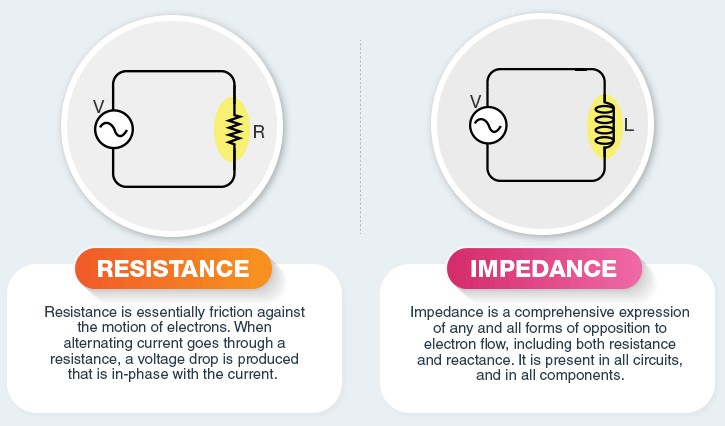
Resistance is a property that opposes the flow of electrical current in a conductor by converting electrical energy into heat, while reactance is a form of opposition that only occurs in alternating current (AC) circuits, affecting the timing between voltage and current. Reactance can be capacitive or inductive, each affecting the circuit in unique ways. The key distinction lies in how they influence the flow of electricity and energy within a circuit.
Where resistance deals with dissipating energy as heat in all types of electrical circuits, reactance introduces a phase shift between current and voltage in AC circuits without dissipating energy. These characteristics are crucial for designing and understanding both basic and advanced electrical systems, impacting everything from household electronics to large-scale power distribution. Our journey through electricity’s fundamentals starts with grasping these two concepts, laying the foundation for exploring their roles in technology and beyond.

Resistance Basics
What is Resistance?
Resistance is a fundamental concept in the realm of electricity and electronics, defining how easily electricity flows through a material. It’s measured in ohms (Ω), and its symbol is typically represented as R. The significance of resistance in a circuit cannot be overstressed; it’s crucial for controlling and managing the flow of electric current. Without resistance, managing electrical energy in circuits would be impractical, leading to uncontrolled current flow and potential damage to circuit components.
Factors Affecting Resistance
The resistance of a conductor is influenced by several key factors:
- Material: Different materials have varying abilities to conduct electricity. Conductors like copper and aluminum offer low resistance, whereas insulators like rubber present high resistance.
- Length: The longer the conductor, the greater the resistance. This is because electrons encounter more collisions along their path, impeding their flow.
- Cross-sectional area: A larger cross-sectional area allows more electrons to flow through, reducing resistance.
- Temperature: Generally, as the temperature of a conductor increases, so does its resistance. This is due to an increase in energy within the atoms, causing more frequent collisions of electrons.
Role in Circuits
In electrical circuits, resistance plays a pivotal role by:
- Limiting the current flow to safe levels, preventing damage to electronic components.
- Dividing voltage in circuits according to the needs of each component, enabling proper functioning of diverse electronic devices.
Reactance Explained
What is Reactance?
Reactance is a measure of the opposition a circuit presents to the change in current or voltage due to inductance or capacitance. Unlike resistance, which is constant, reactance varies with the frequency of the electrical signal. It’s significant in AC (Alternating Current) circuits, where the current’s direction changes periodically. Reactance is measured in ohms (Ω) and symbolized by X.
Types of Reactance
Reactance comes in two main types:
- Capacitive reactance (Xc): Opposition to the change in voltage in a capacitor. It decreases with increasing frequency.
- Inductive reactance (Xl): Opposition to the change in current in an inductor. It increases with increasing frequency.
These two types of reactance have opposite effects on a circuit’s impedance, affecting how AC signals are transmitted.
Factors Influencing Reactance
The key factors influencing reactance include:
- Frequency: The primary factor affecting reactance. Higher frequencies increase inductive reactance and decrease capacitive reactance.
- Component characteristics: The physical properties of capacitors and inductors, such as capacitance and inductance values, directly impact their reactance.
Resistance vs. Reactance
Core Differences
While resistance and reactance both oppose electrical flow, they differ fundamentally in their behavior and effects:
- Time-dependence: Reactance varies with frequency, while resistance is constant regardless of frequency.
- Energy dissipation: Resistance results in energy being dissipated as heat, whereas reactance causes a temporary storage of energy, which is then returned to the circuit without dissipation.
Impact on Circuit Behavior
The presence of resistance and reactance in a circuit influences its behavior significantly:
- Phase angle: Reactance causes a phase shift between voltage and current in an AC circuit, which does not occur with pure resistance.
- Power factor: A circuit containing reactance will have a power factor less than 1, indicating that some of the power is reactive rather than real. This affects the efficiency of power delivery in AC systems.

Measuring and Calculating
Tools and Techniques
Multimeters and LCR Meters
To measure resistance and reactance, professionals use multimeters and LCR meters. Multimeters, versatile tools found in every electrician’s toolkit, can measure resistance directly by passing a small current through the component and measuring the voltage drop. For reactance, LCR meters are the go-to instruments. These are specialized to measure the inductance (L), capacitance (C), and resistance (R) of components, providing insights into their reactive properties at varying frequencies.
Key Formulas
Calculations for Resistance and Reactance
Calculating resistance and reactance involves fundamental formulas that are critical for circuit analysis:
- Resistance (�R) can be calculated using Ohm’s Law: �=�/�R=V/I, where �V is voltage and �I is current.
- Capacitive reactance (��XC) is given by ��=1/(2���)XC=1/(2πfC), with �f representing frequency and �C capacitance.
- Inductive reactance (��XL) is calculated using ��=2���XL=2πfL, where �L is inductance.
Practical Applications
In Electronics
Filtering, Timing, and Control Circuits
In electronic circuits, resistance and reactance play vital roles in filtering, timing, and control mechanisms. Filtering circuits, for instance, rely on capacitors (capacitive reactance) and inductors (inductive reactance) to block unwanted frequencies while allowing desired signals to pass. Timing circuits use the RC (resistor-capacitor) or LR (inductor-resistor) time constants to create delays. Control circuits leverage these components to regulate current and voltage, ensuring devices operate within safe parameters.
In Power Systems
Transmission Lines and Transformers
In power systems, the concepts of resistance and reactance extend to transmission lines and transformers, ensuring efficient electricity distribution. Transmission lines exhibit both resistance and reactance, affecting power flow and voltage levels over long distances. Transformers, essential for changing voltage levels, also experience reactance, impacting their ability to deliver power efficiently.
Challenges and Solutions
Dealing with Reactance
Compensators and Tuning
To mitigate issues caused by reactance in AC systems, engineers use compensators and tuning methods. Compensators adjust the circuit’s reactance to improve power factor and reduce energy loss. Tuning, particularly in resonance circuits, aligns the system’s natural frequency with the operating frequency, optimizing performance.
Managing Resistance
Material Selection and Design Optimization
Managing resistance involves strategic material selection and design optimization. Conductors with low resistivity, such as copper and aluminum, are chosen for their efficiency. Design optimizations, including minimizing conductor lengths and maximizing cross-sectional areas, reduce resistance to enhance performance and energy efficiency.
Future Perspectives
Advances in Materials
Superconductors and Nanotechnology
The future of electrical engineering shines bright with the advent of superconductors and nanotechnology. Superconductors, materials that exhibit zero resistance below a certain temperature, promise revolution in power transmission and magnetic levitation. Nanotechnology, with its potential to manipulate materials at the atomic level, could lead to ultra-efficient, miniaturized electronic components.
Innovations in Design
Smart Circuits and Adaptability
Innovation continues with the development of smart circuits capable of adapting to changing conditions. These advanced systems can self-regulate resistance and reactance, ensuring optimal performance under varying electrical loads and frequencies. This adaptability paves the way for more resilient and efficient electrical and electronic systems.
FAQs
What is electrical resistance?
Electrical resistance is the property of a material that opposes the flow of electric current, converting part of the electrical energy into heat. It is a constant value in a circuit regardless of the frequency of the applied voltage and plays a critical role in determining the amount of current flowing through an electrical circuit.
How does reactance differ from resistance?
Unlike resistance, which is present in both direct current (DC) and alternating current (AC) circuits, reactance occurs only in AC circuits. Reactance causes a phase shift between the voltage and current in a circuit without converting energy into heat. It can be either capacitive or inductive, depending on the nature of the components in the circuit.
Why is understanding resistance and reactance important?
Understanding resistance and reactance is crucial for designing and troubleshooting electrical and electronic circuits. It helps in determining the behavior of circuits under different conditions, optimizing circuit performance, and ensuring energy efficiency. Knowledge of these concepts is also vital for the safe and effective application of electrical technology in various domains.
How are resistance and reactance measured?
Resistance is measured in ohms (Ω) using tools like multimeters, which apply a known voltage to determine the current flowing through a component. Reactance is also measured in ohms but requires the use of an LCR meter or similar device capable of analyzing the circuit’s response to an AC signal, considering the frequency-dependent nature of reactance.
Conclusion
Grasping the differences between resistance and reactance illuminates the nuanced behaviors of electricity in various circuits and applications. This understanding is not just academic; it serves as a fundamental pillar in the design, analysis, and optimization of all things electrical. From the simplest circuits in household gadgets to the complex networks in power systems, the interplay of resistance and reactance shapes the efficiency, safety, and effectiveness of electrical technologies.
Encouraging deeper exploration into these concepts opens up a world of innovation and understanding in electrical engineering and physics. As we continue to push the boundaries of technology, the principles of resistance and reactance will remain central to our efforts, guiding us towards smarter, more efficient, and more sustainable electrical solutions.